|
|
Step 9-13 : Building the Hardware
Step 11 - Stand Alone Version - with GPS :
Site is being updated however please start here for these esp8266 builds.
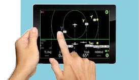
We will describe the first GPS version here, this can be used as a standalone device that a pilot can carry to just broadcast their position or can be connected to a Kobo or any serial interface with a 2 pin lead, it can be also configured back to a Wifi version if required.
We have found the Kobo wifi to be ok, it can disconnect itself sometimes and then take a while to reconnect, or you can reconnect manually, the hard wired version doesnt suffer from any of these disconnections and works 24/7.
Please log into the Air-ware webpage and switch the connection mode to hardwired to use this version.
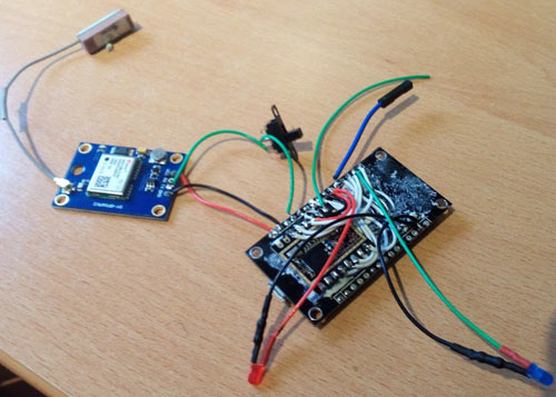
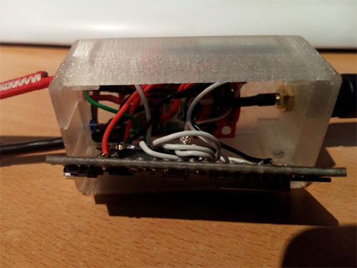
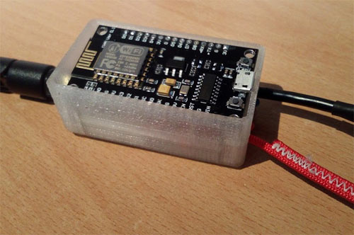
We usually just use some double sided tape to attach the RF module to the side of the ESP, the same as the wifi version, then a GPS unit is added, this can be mounted in the bottom of the case with the same tape and then the node and rf module mounted in the case. The following picture shows the gps wired to the nodemcu, the switch is there to be able to flash the board again for programming, its not required for normal use, the wire attached to D4 can be used to connect to an FTDI converter to see the GPS lines coming from the system, please contact us for details if you wish to do this.
The Baud rate setting for this version for the Kobo to read the data coming in is 57600. Your serial port setting for your GPS should remain the same as usual, this is setup in the webpage, in the configuration, usually 9600, /dev/ttymxc0 , 8bit. The GPS baud rate and the Kobo baud rate are a different channel of communication, the GPS communicates with the Node and the Node communicates with the Kobo therefore they need setting independantly.
Building Diagnostics - Please view the Building diagnostic Page before you get started, make sure you hardware is all working correctly.
Please follow the diagram below to wire the RF Lora module to the ESP module, be a bit careful with the wiring of the USB lead, some leads I have found are not correctly coloured, one we found was red negative and white positive, just make sure your wiring the correct polarity. Another thing to watch out for is the ground LED is the shorter of the two on the LED.
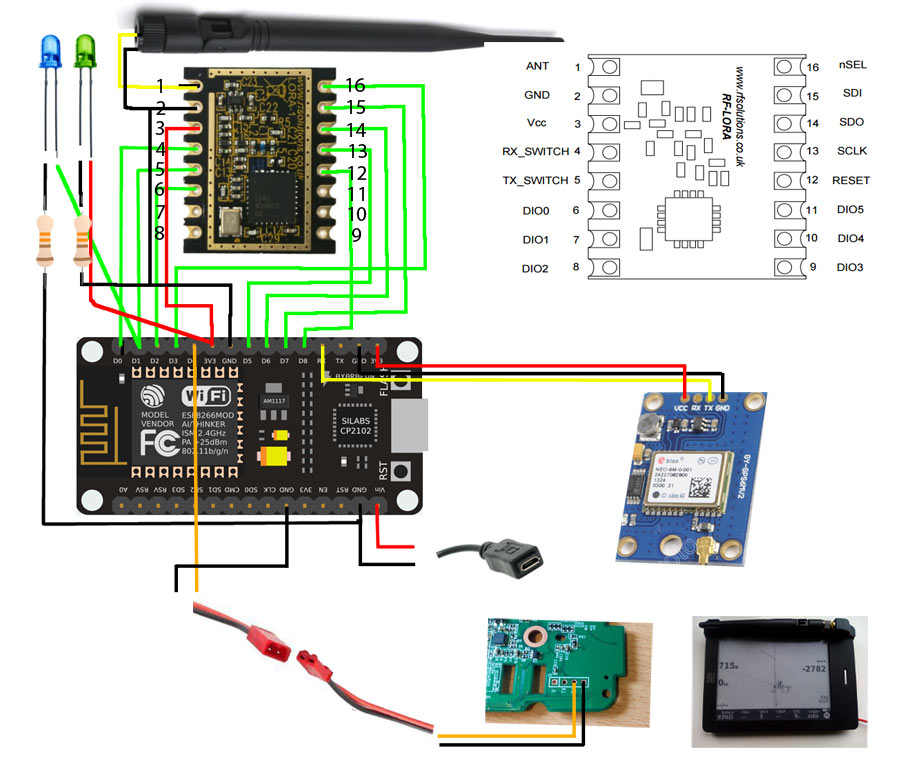
The following pinouts can be also used.
| Nodemcu | RF LORA | Aerial | Power LED | Transmission LED | USB | GPS | Kobo |
| D0 | 4 | | | | | | |
| D1 | 5 | | | +ve | | | |
| D2 | 6 | | | | | | |
| D3 | 16 | | | | | | |
| D5 | 13 | | | | | | |
| D6 | 14 | | | | | | |
| D7 | 15 | | | | | | |
| D8 | 12 | | | | | | |
| RX | | | | | | TX | |
| 3V | 3 | | +ve | | | +ve/VCC | |
| GND | 2 | Outer | -ve | -ve | -ve | -ve/GND | GND/-VE |
| VIN | | | | | +ve | | |
| 1 | Inner | | | | | |
| D4 | | | | | | | RX |
PLEASE MAKE SURE YOUR GPS HAS A FIX FOR TESTING!
(easy thing to miss when testing and you think your wiring is wrong and its not ! )
When this has been done plug the unit into the 5 volt USB power source and then connect your chosen flight computer to the unit and when the unit receives a GPS fix the transmission light ( connected to pin D1 on the ESP or 5 on the RF Lora ) should flash, once the this light is flashing then the unit should be fully operational and be able to receive aswell.
Please make sure you have 3volt GPS, if you have a 5volt you can attach it to Vin instead of 3v, this will power it, check the GPS manual for details.
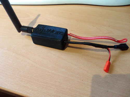
We have a custom made case that can be printed for the wifi version, please download from thingiverse or contact us for a printed one.
Few pictures below on how we installed the unit, bit of a squeeze but fits well, make sure you use double sided tape to attach the GPS to roof of the box to keep it out of the way
General Tips
Tools - there will be the obvious ones for soldering and small work but here’s what I found invaluable.
● A pair of flip down magnification glasses, preferably with a LED light mounted.
● Sharp tip tweezers.
● Helping hands / mounted croc clips.
● 15 watt iron with a 2 to 4mm tip seem okay.
Soldering technique. The node and LoRa module seem fairly heat and static tolerant but the
assembly is delicate work so it pays to get it right.
● You’re aiming for 2 or 3 seconds contact to solder the joint with a nice silvery finish
and blob shape.
● Use a damp cloth to wipe the iron clean before each use.
● Wet the iron with some fresh solder before contact.
● Don’t hang about in there, either your joint will run silvery or contact is not good and
you’re just heating the board or components. Reclean and wet the iron and try again
after giving the joint a chance to cool.
Any GND will do for LEDs etc - there’s about four on the node board. Stick to the single GND
on the LoRa module for the antenna though.
With single strand wire and component legs put a tiny (1mm) bend in the end of the leg. It
helps hook it into the hole if you’re laying the wires in horizontally to the boards.
If you don’t have heat shrink for floating wire joints then folding a bit of sellotape over the
joint is fine.
● Prebend the antenna pigtail wire before inserting the board into the case. It’ll avoid
strain on the antenna solder joints when in the case.
● The double GND power & GND antenna joint is the hardest on the LoRa module
because the antenna shielding tends to be thicker. You can cut it down or solder it on
top of the existing GND power wire. This give is a bit of height over the LoRa module
so they don’t come into contact.
● Don’t share the GND wire and resistor for the GND legs of the power and data LEDs.
It’s tempting but I had problems with the data LED lighting up in this configuration.
Take both LEDs through their own resistors to GND.
● Tape kitchen foil between suitable, larger pieces of paper and insulating tape when
attaching the LoRa module to the node. It should give a little extra resistance to
interference.
● If using a USB socket for the power connector double check the polarity before wiring
it into VIN and GND on the node. Mine had white +ve 5V and red -ve. Obviously a
Friday afternoon cable!
● It’s helpful if you use single core wire between the node and LoRa module. Bend
them into shape and added together they’ll hold the whole lot together better than
tape alone.
● It’s also helpful if the wires out to the LEDs and power are multi strand flexible as
they need a bit of jimmying to get them into the case.
|
|
|
|
|
|