|
|
Step 9-13 : Building the Hardware
Step 10 :
We will describe the wifi version here which is the simplest.
Before starting to mount into a case please check your hardware is ok by following this diagnostic page
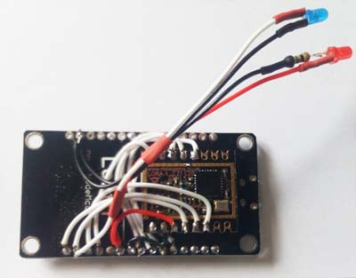
We usually just use some double sided tape to attach the RF module to the side of the Nodemcu, use a couple of pieces of thick double sided tape to space the RF Lora away from the Nodemcu to stop interference, perhaps even 3 so that both boards are around 5mm apart, whatever you can do fit it in the box, then wire it up as shown below, the picture shows one resistor being used on the power light, but its best to add a resistor to both LED's. If your Nodemcu board comes with pins we have found the best way to remove them is to clip the ends off as far as you can with wire clippers and then with the same clippers pull the black plastic base off, then unsolder each one individually, takes 5 mins. The USB power lead and the Aerial lead arent soldered onto the board in the following picture as these arent necessary to check your wiring and you can now test to see if the GPS lines are still coming back into the flight computer, also the Transmit LED should flash.
Please follow the diagram below to wire the RF Lora module to the Nodemcu module, be a bit careful with the wiring of the USB lead, some leads I have found are not correctly coloured, one we found was red negative and white positive, just make sure your wiring the correct polarity. Another thing to watch out for is the ground LED is the shorter of the two on the LED. Any of the grounds (G) on the Nodemcu can be used, just use the most convenient nearest one for your install.
The Vin and GND on the Nodemcu take 5volt DC, if you wanted to wire it to a 3.7V lipo battery then wire into one of the 3V pins.
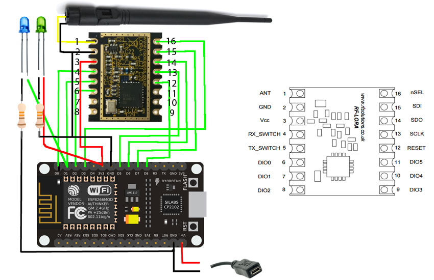
The following pinouts can be also used.
| Nodemcu | RF LORA | Aerial | Power LED | Transmission LED | USB |
| D0 | 4 | | | | |
| D1 | 5 | | | +ve | |
| D2 | 6 | | | | |
| D3 | 16 | | | | |
| D5 | 13 | | | | |
| D6 | 14 | | | | |
| D7 | 15 | | | | |
| D8 | 12 | | | | |
| 3V | 3 | | +ve | | |
| GND | 2 | Outer | -ve | -ve | -ve |
| VIN | | | | | +ve |
| 1 | Inner | | | |
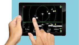
When this has been done plug the unit into the 5 volt USB power source and then connect your chosen flight computer to the unit and when the unit receives a GPS fix the transmission light (connected to pin D1 on the Nodemcu or 5 on the RF Lora) should flash, once the this light is flashing then the unit should be fully operational and be able to receive aswell.
PLEASE MAKE SURE YOUR GPS HAS A FIX FOR TESTING!
(easy thing to miss when testing and you think your wiring is wrong and its not ! )
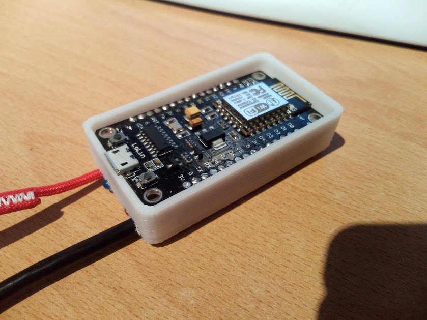
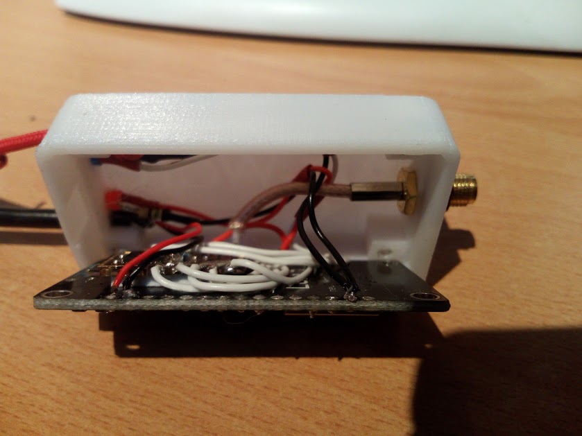
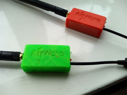
We have a custom made case that can be printed for the wifi version, please download from thingiverse or contact us for a printed one.
Few pictures below on how we installed the unit, bit of a squeeze but fits well.
|
|
|
|
|
|